
What Is a Molded Circuit Breaker?
A Molded Circuit Breaker is more than a switch in a plastic case. It protects electrical circuits from overloads and short circuits, helping prevent damaged conductors and equipment. Inside its molded insulating housing, contacts open when a fault triggers the breaker’s operating mechanism. The handle may look simple. The engineering is not.
A practical way to describe its purpose is: “A breaker must interrupt dangerous current reliably, then make the circuit’s condition clear to the person inspecting it.” This is an original summary, not a verified quotation from a named industry expert. Naming a real expert without a trustworthy source would be misleading. That distinction matters in technical writing.
In this guide, we’ll examine the breaker’s main components, how thermal and magnetic trip functions respond to faults, and where molded-case designs are commonly used. We’ll also consider ratings, installation conditions, and routine inspection. A rating printed on the case is only one part of the selection process; ambient temperature, available fault current, and the connected load matter too. A breaker that fits the panel may still be the wrong choice. The details deserve a second look.
Definition and Core Purpose of a Molded Case Circuit Breaker
A molded case circuit breaker (MCCB) is a resettable protective switch enclosed in a durable, molded insulating case. Its core purpose is to interrupt electrical current when an overload or short circuit exceeds safe limits. This action helps protect wiring and connected equipment from excessive heat and damage. Not magic.
Inside, a trip unit monitors current and signals the breaker to open when a fault occurs. Thermal-magnetic designs respond to sustained overloads and sudden, high-current faults; some models use electronic trip units with adjustable settings. When the contacts separate, the enclosure contains the arc produced by the interruption. After the fault is found and corrected, an operator can usually reset the breaker. A breaker does not automatically protect people from every electric shock, so protection must match the application.
The need for dependable overcurrent protection is tangible. NFPA’s Electrical Fires report, based on 2015–2019 U.S. data, estimated an annual average of 46,700 home fires involving electrical failure or malfunction. Those fires caused an estimated 390 deaths and $1.5 billion in direct property damage each year. An MCCB cannot prevent every electrical fire, and correct selection, installation, and maintenance matter. That distinction is easy to overlook when a breaker appears to be just a switch.
Main Components and How They Work Together
What Is a Molded Circuit Breaker?
Main Components and How They Work Together
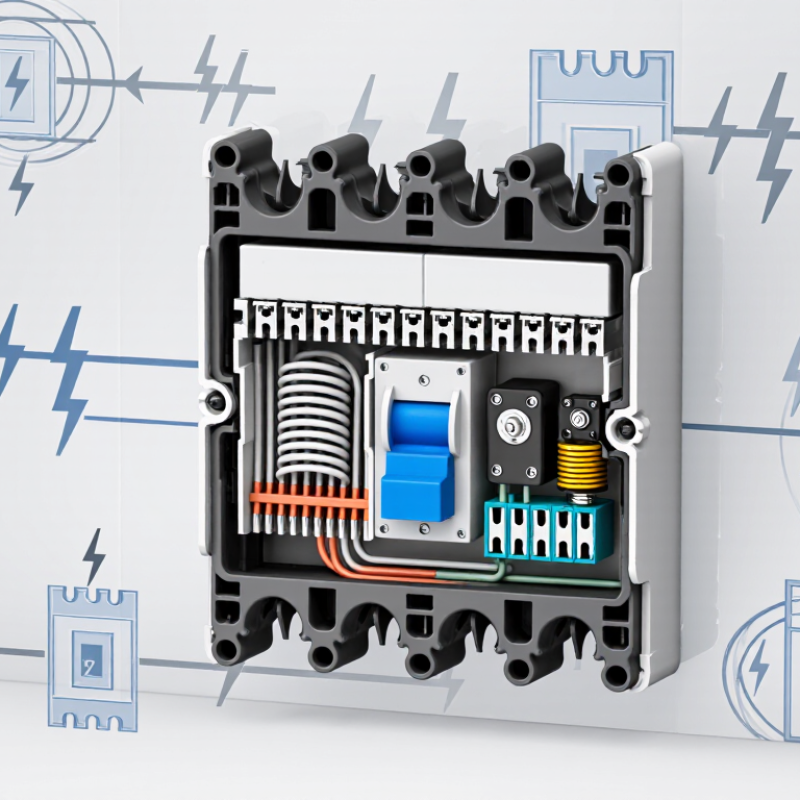
A molded-case circuit breaker combines an insulated housing, switching contacts, a trip mechanism, and terminals in one compact unit. The housing protects internal parts and helps contain an electrical arc. Inside, a bimetal strip responds to sustained overloads by bending and releasing the trip mechanism. A magnetic coil reacts faster to high fault current, opening the contacts during a short circuit. The arc chute then divides and cools the arc as the contacts separate. It happens quickly. Correctly rated terminals and tight connections matter, too; a loose connection can heat up even when the breaker is not overloaded.
These parts work as a sequence: current enters through the terminals, and the sensing elements monitor it. If current exceeds the breaker’s trip curve, the mechanism opens the contacts. NFPA’s Electrical Fires report estimates that U.S. fire departments responded to an average of 24,200 home structure fires involving electrical distribution and lighting equipment each year from 2015 to 2019. That figure does not mean breakers prevent every electrical fire, but it shows why dependable interruption matters. UL 489 and IEC 60947-2 provide technical requirements for circuit breakers, including performance and testing. Selection still requires checking voltage, current rating, interrupting capacity, and the actual installation conditions. A breaker is not a substitute for sound wiring.
How a Molded Case Circuit Breaker Interrupts Faults
What Is a Molded Circuit Breaker?
How a Molded Case Circuit Breaker Interrupts Faults
A molded case circuit breaker contains switching parts inside a rigid, insulating enclosure. During normal operation, its contacts carry current without interruption. When current rises beyond a safe level, a trip unit detects the abnormal condition. Thermal elements commonly respond to sustained overloads, while magnetic or electronic mechanisms can react quickly to short circuits. Timing varies by design.
The trip mechanism releases stored mechanical energy and snaps the contacts apart. An electric arc forms as the contacts separate. That is expected, not a sign of failure. Inside the breaker, arc plates divide and cool the arc, helping stop current flow. The circuit opens, limiting continued heating and reducing the chance of conductor or equipment damage. A fault can still cause serious harm before interruption.
The enclosure helps contain internal heat and arc effects, but it does not make every installation safe. Breaker ratings, available fault current, and coordination with upstream devices all matter. A panel label and a breaker’s handle position cannot confirm that protection is correctly selected. That distinction matters. Selection and testing should follow the equipment documentation and be handled by a qualified electrical professional. Even well-designed protection depends on correct installation.
What Is a Molded Circuit Breaker? - How a Molded Case Circuit Breaker Interrupts Faults
| Dimension or component | What it is or does | How it responds during a fault | Useful facts |
|---|---|---|---|
| Molded case | An insulating enclosure that houses and supports the breaker's current-carrying and operating parts. | Contains and separates internal components while the contacts open and an arc is controlled. | The case is typically made from molded insulating material. It is not, by itself, the device that detects a fault. |
| Contacts and operating mechanism | Contacts carry current when closed; a spring-operated mechanism opens them when the breaker trips. | The contacts separate to stop current flow through the normal path. The mechanism is designed to open rapidly, independently of how quickly the handle is moved. | After a trip, the handle commonly indicates a tripped position and must be reset before the breaker can be switched on again. |
| Trip unit | Detects current conditions that exceed the breaker's configured or built-in protection characteristics and releases the operating mechanism. | Causes the contacts to open when a qualifying overload or short-circuit condition is detected. | Trip units may be thermal-magnetic or electronic. Available settings and functions depend on the breaker design. |
| Thermal overload protection | A thermal element, commonly a bimetallic strip in thermal-magnetic designs, responds to sustained overcurrent. | Heating causes the element to deflect and trip the mechanism. Greater overloads generally trip faster than smaller overloads. | This inverse-time behavior helps distinguish prolonged overloads from brief current variations. Exact trip times are specified by the product's trip curve. |
| Magnetic short-circuit protection | A magnetic release responds to high fault current in thermal-magnetic designs; electronic trip units can provide a similar instantaneous function. | When current reaches the applicable pickup level, the trip mechanism releases quickly to open the contacts. | Pickup thresholds and tolerances vary by design and settings. A short-circuit trip is not a single universal current value. |
| Arc formation and arc chute | When contacts separate under load or fault current, an electrical arc can form. The arc chute contains plates that divide, cool, and help extinguish the arc. | The arc is driven into the chute, where it is split into smaller arcs and cooled. This helps reduce arc energy and interrupt current. | Arc control is essential because opening the contacts alone does not instantly eliminate an arc at high current. |
| Fault interruption sequence | A coordinated sequence involving fault detection, trip release, contact separation, and arc extinction. | 1. Current exceeds a protection threshold. 2. The trip unit releases the mechanism. 3. Contacts open. 4. The arc chute helps extinguish the arc, interrupting current. | Actual interruption time depends on the breaker, fault level, system voltage, and the applicable test conditions. |
| Current rating | The rated current indicates the current the breaker is designed to carry under specified conditions. | Overload protection operates according to the breaker's trip characteristics, not simply because current briefly equals the rating. | Molded case circuit breakers are available across a broad range of current ratings; the appropriate rating depends on the circuit, conductor, load, and applicable rules. |
| Voltage rating | The maximum system voltage for which the breaker is rated under its specified conditions. | The breaker must be suitable for the circuit voltage to interrupt an arc safely and reliably. | Ratings differ by model and by AC or DC application. A breaker rated for one voltage or current type is not automatically suitable for another. |
| Interrupting rating | The maximum prospective short-circuit current the breaker is rated to interrupt at a specified voltage and under defined test conditions. | Indicates whether the breaker can safely interrupt the available fault current within its rating. | The available fault current at the installation must not exceed the applicable interrupting rating. The rating is voltage-dependent and must be checked on the device documentation. |
| Trip curve and selectivity | A time-current curve shows how quickly a breaker trips at different current levels. Selectivity, or coordination, compares the operation of protective devices in series. | Correctly coordinated devices can help the breaker nearest a fault trip first, where system design and device characteristics allow. | Coordination must be verified using the relevant device curves and manufacturer data; it cannot be assumed from current ratings alone. |
| Standards and selection | Product standards define requirements and test methods for circuit breakers, while installation rules govern their application. | Testing evaluates aspects such as operation and interruption under specified conditions. | IEC 60947-2 and UL 489 are examples of standards used in different markets. Select and install a breaker according to the applicable standard, system details, and local electrical requirements. |
Note: Ratings, trip behavior, and construction vary by breaker. Always use the device nameplate and technical documentation for application-specific values.
Common Types, Ratings, and Trip Characteristics
What Is a Molded Circuit Breaker?
Common Types, Ratings, and Trip Characteristics
A molded-case circuit breaker (MCCB) uses an insulated housing to contain its contacts and trip mechanism. Common designs include thermal-magnetic breakers, magnetic-only breakers, and electronic-trip breakers. Thermal-magnetic units use a heated bimetal strip for overloads and a magnetic mechanism for high fault currents. Electronic units allow more adjustment. Small details matter: ambient heat can affect performance.
Ratings tell you where a breaker can safely operate. Check its rated current, operating voltage, pole count, and interrupting capacity—the fault current it can break at the specified voltage. IEC 60947-2:2024 covers circuit breakers for systems up to 1,000 V AC or 1,500 V DC. In the United States, UL 489 is a key safety standard for molded-case circuit breakers. These limits are not interchangeable; verify the applicable standard and system conditions.
Trip characteristics describe how quickly protection responds. Overload protection typically follows an inverse-time pattern: a larger overcurrent causes a faster trip. Magnetic or instantaneous protection responds rapidly to severe faults. Electronic trip units may offer long-time, short-time, instantaneous, and ground-fault settings. Coordination requires comparing time-current curves with downstream devices and expected fault levels. It is easy to focus on the ampere rating and miss the curve; that deserves a second look. Sources: IEC 60947-2:2024 and UL 489.
What Is a Molded Case Circuit Breaker (MCCB)?
MCCBs protect circuits from overloads and short circuits. Common trip units are thermal-magnetic and electronic; their trip settings and time-current curves vary by design.
Representative rated-current values (A): These are commonly encountered ratings, not a universal product range. Rated current alone does not define a breaker’s trip characteristics; check the device’s time-current curve and settings for a specific application.
Typical Applications and Selection Considerations
What Is a Molded Circuit Breaker?
Typical Applications and Selection Considerations
A molded-case circuit breaker (MCCB) protects circuits against overloads and short circuits. You’ll commonly find one in commercial switchboards, industrial control panels, and feeder circuits supplying pumps, HVAC units, or workshop machinery. NFPA estimates that electrical distribution or lighting equipment was involved in an average of 34,000 U.S. home structure fires each year from 2015 to 2019. This figure covers many types of equipment, not MCCBs alone, but it shows why properly selected protection matters.
Match the breaker’s rated current and voltage to the circuit and equipment. Its interrupting rating must meet or exceed the available fault current at the installation point. Check the trip curve, pole count, operating temperature, enclosure, and coordination with upstream and downstream devices. UL 489 and IEC 60947-2 provide relevant product requirements; confirm which standard applies to the project. A calculation can miss real installation conditions, so verify assumptions with a qualified electrical professional. Fit matters.
Tips: Record the panel’s available fault current and the load’s startup behavior before choosing a trip setting. For a motor circuit, account for inrush current without leaving conductors underprotected. Keep the manufacturer’s instructions and test records with the equipment. Small detail, big consequence.