
China Top Safety Contactor Manufacturers and Suppliers
Choosing a Safety Contactor is not just a matter of comparing prices or coil voltages. In a machine cabinet, the device must work with the safety circuit, stop hazardous motion, and provide feedback that the control system can monitor. Small details matter: contact configuration, rated current, switching frequency, and compatibility with the selected safety relay or controller. A mismatch can complicate validation and maintenance.
The scale of industrial automation makes careful selection increasingly important. The International Federation of Robotics’ World Robotics 2024 report recorded 4,281,585 industrial robots operating in factories worldwide at the end of 2023, a 10% increase over 2022. This figure is not a measure of contactor sales, but it illustrates the expanding automated environment where dependable machine-safety components are needed. IEC 60947-4-1 provides requirements for electromechanical contactors and motor-starters; machine designers must also consider applicable functional-safety standards and the complete control system. Safety-science expert James Reason wrote, “We cannot change the human condition, but we can change the conditions under which humans work.” His words are a useful reminder: component choice supports safe design, but cannot replace it.
This guide introduces leading China-based Safety Contactor manufacturers and suppliers, with attention to product range, technical documentation, quality controls, and export support. Buyers should verify certifications and test evidence for each specific product, rather than relying on broad company claims. A polished catalog is helpful. It is not proof.
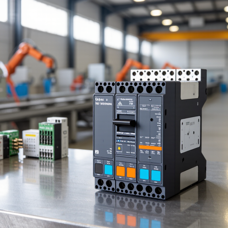
Safety Contactors Defined: IEC 60947-4-1 Covers Up to 1,000 V AC
Safety contactors are electromechanical switching devices used to disconnect motors or other loads when a control system detects a hazardous condition. IEC 60947-4-1 is a key reference for contactors and motor-starters. It covers equipment rated up to 1,000 V AC, an important boundary when comparing technical specifications. The standard also covers certain DC applications up to 1,500 V. That detail is easy to overlook. Its requirements address device performance, coordination, and testing, but they do not replace a machine-level risk assessment or safety-system design.
When reviewing a contactor, check its rated operational voltage, current, utilization category, and short-circuit coordination data. For safety-related applications, confirm whether the device provides mechanically linked or mirror contacts for feedback monitoring. A supplier’s catalogue should state these details clearly, alongside relevant test documentation. Do not assume that “safety” on a product description guarantees suitability for every circuit. That deserves a second look. Installation conditions matter too: cabinet temperature, switching frequency, and motor load can affect service life. Compare the actual application with the published ratings, and ask for clarification when a specification leaves room for interpretation.
How Safety Contactors Work: Mirror Contacts, Redundancy, and Fault Monitoring
Inside a safety circuit, a contactor disconnects power when a machine guard opens or an emergency stop is pressed. An IEC 60947-4-1 mirror contact is mechanically linked to the contactor’s main contacts. If a main pole welds, the normally closed mirror contact cannot close. The safety controller can detect that mismatch and block a restart. That small detail matters. Redundancy may use two contactors in series, but extra hardware alone does not guarantee safety. Both channels need suitable monitoring and wiring.
External device monitoring checks the contactors’ feedback before allowing reset. This can reveal a welded contact, a broken feedback wire, or a failed device. IEC 60947-4-1 covers contactor requirements, while ISO 13849-1 addresses safety-related control system design.
These figures are not proof that a contactor prevents injury; they show why dependable safety functions matter. In practice, wiring drawings are not always as tidy as the manual suggests. Commissioning tests and documented reset checks can expose gaps before production starts.
Key Specifications: AC-3 Ratings, Coil Voltage, B10d, and Switching Life
China Top Safety Contactor Manufacturers and Suppliers
Key Specifications: AC-3 Ratings, Coil Voltage, B10d, and Switching Life
When comparing safety contactors from Chinese manufacturers and suppliers, start with the AC-3 rating. It describes performance when starting and stopping squirrel-cage motors, not every possible load. Check the rated current and operating voltage together. A contactor selected only by motor power may be undersized under frequent switching or demanding conditions. Numbers need context.
Coil voltage must match the control circuit, including whether its supply is AC or DC. Confirm the permitted voltage range and check what happens during voltage dips. In a real cabinet, a label can be hard to read once wiring is crowded. Ask suppliers for clear wiring diagrams and test reports tied to the exact model. Small detail, big consequence.
B10d indicates the number of operations at which 10 percent of a tested population may have experienced dangerous failures under stated conditions. It is not a guaranteed service life for every installation. Compare the test conditions, load, and switching frequency with your application. Also distinguish mechanical life from electrical switching life; motor loads can wear contacts faster. A polished datasheet is useful, but it cannot replace evidence. I would still ask how the figures were verified, and admit that published values may not mirror a dusty, hot panel running every day.
China’s Leading Safety Contactor Manufacturers: Products and Certifications
China’s safety contactor manufacturers supply devices for machinery, control cabinets, and automated production lines. A typical unit switches motor power while auxiliary contacts support monitoring in a safety circuit. Buyers should check rated operational current, coil voltage, switching frequency, and expected electrical life. These details matter. A contactor selected for a 400-volt motor may still be unsuitable if its utilization category or control arrangement does not match the application.
Product ranges often include compact contactors, auxiliary contact blocks, and assemblies intended for redundant switching. For safety functions, engineers should examine mirror-contact behavior and confirm that the device works with the chosen safety relay or controller. A neat datasheet is useful, but it cannot replace testing in the actual cabinet. Wiring length, heat, and frequent starts can change operating conditions. This part is easy to underestimate.
Certifications and test documents need careful review. IEC 60947-4-1 is relevant to contactors and motor starters, while other standards may apply to related control components. Some suppliers also provide market-specific conformity documents. Verify the exact model, ratings, issuing body, and certificate scope; documents for one product do not automatically cover an entire range. Ask for traceable test reports and production inspection records. One small caution: certificates do not prove suitability for every safety architecture. Application-level risk assessment still matters.
China’s Leading Safety Contactor Manufacturers: Products and Certifications
Publication years of key international standards relevant to contactors, machine electrical equipment, and functional safety.
These standards provide useful reference points when assessing safety-related control products. A standard’s publication does not confirm that a particular product is certified; verify the certificate, applicable edition, and product scope with the supplier.
Supplier Verification: ISO 13849 PL a–e and IEC 62061 SIL 1–3
China Top Safety Contactor Manufacturers and Suppliers
Supplier Verification: ISO 13849 PL a–e and IEC 62061 SIL 1–3
A safety contactor is only one part of a machine’s safety-related control system. Supplier checks should examine the complete function: sensors, logic, switching devices, wiring, and reset behavior. Ask for calculations and validation records, not a certificate alone. On a real panel, inspect terminal markings and the feedback loop, too. Small details matter.
ISO 13849-1:2023 defines Performance Levels from PL a to PL e. Its dangerous-failure probability ranges from 10⁻⁵ to below 10⁻⁴ per hour for PL a, down to 10⁻⁸ to below 10⁻⁷ for PL e. IEC 62061:2021 sets SIL 1–3 ranges for high-demand or continuous modes: 10⁻⁶ to below 10⁻⁵, 10⁻⁷ to below 10⁻⁶, and 10⁻⁸ to below 10⁻⁷ per hour. These figures come from the standards, not a supplier’s marketing sheet.
Check that the stated PL or SIL matches the machine risk assessment and the intended operating conditions. PL and SIL are related measures, but they are not interchangeable labels. Request component reliability data, diagnostic coverage assumptions, and proof-test requirements where applicable. Then review whether the proposed circuit supports the claimed target. Paperwork can look neat. Field validation may still reveal gaps. A careful supplier should explain those limits plainly.
| Verification Dimension | Information to Request | How to Verify | Acceptance Considerations |
|---|---|---|---|
| Product identity and ratings | Exact product type, operating voltage, rated operational current, utilization category, switching frequency, and electrical endurance. | Compare the product label, technical datasheet, and test documentation. Confirm the stated ratings cover the intended load and duty cycle. | Do not treat a general-purpose contactor rating as proof of suitability for a safety function. Check the actual load, fault conditions, and application limits. |
| Safety-related contact characteristics | Details of mirror contacts or mechanically linked contacts, where provided, including their intended function and applicable test evidence. | Request the relevant technical declaration and supporting test information. Check that the auxiliary contact arrangement matches the feedback-monitoring circuit design. | Contact characteristics must be verified for the specific device and wiring arrangement; they do not, by themselves, establish a PL or SIL rating for the complete safety function. |
| ISO 13849-1 performance data | Safety-related reliability data needed for the design, such as B10d or MTTFd data, diagnostic coverage assumptions, and restrictions on use. | Request the manufacturer’s safety manual or reliability data and record the model and operating conditions to which the values apply. | PL a–e is determined for the safety-related control system or subsystem using the applicable architecture and reliability data. A component alone should not be assumed to achieve a stated PL. |
| ISO 13849-1 architecture and diagnostics | Guidance on suitable channel arrangements, feedback monitoring, fault detection, and any required external measures. | Review the proposed safety circuit and validate it using an appropriate calculation or assessment method. Check that diagnostic assumptions are implemented in the actual design. | Category, MTTFd, DCavg, and measures against common-cause failure contribute to the assessment. The achieved PL depends on the complete design. |
| IEC 62061 safety data | PFHd or other applicable safety-related data, subsystem limitations, and any SILCL information stated for the product or subsystem. | Request the supporting safety documentation and verify that the data apply to the exact product variant and operating conditions. | SIL 1–3 is assessed for the safety function or subsystem under IEC 62061. A component’s SILCL or reliability data alone do not demonstrate that the complete machine safety function meets a SIL target. |
| Standards and conformity documentation | Applicable standards, declarations, certificates where applicable, report references, and the issuing organization’s details. | Check document numbers, scope, product identifiers, issue dates, and validity directly with the issuing body where possible. | Distinguish a supplier declaration from independent certification or test evidence. Confirm that documents cover the exact product and intended application. |
| Electrical endurance and switching conditions | Rated utilization category, expected switching operations, load type, short-circuit coordination guidance, and permitted ambient conditions. | Compare application requirements with the datasheet and installation instructions. Request test conditions where endurance figures are important to the safety calculation. | Electrical life can differ significantly with load and switching conditions. Use the specified conditions rather than assuming a single endurance figure applies universally. |
| Quality and change control | Quality-management documentation, traceability information, revision control, and notification procedures for product or component changes. | Review current quality documents and confirm how production batches and technical revisions can be traced. | Quality-system credentials support supplier assessment but do not replace product-specific safety evidence or validation of the machine-level safety function. |
| Supplier document consistency | Datasheet, safety manual, drawings, certificates, and quotations that identify the same model and revision. | Cross-check model codes, ratings, terminal layouts, document revisions, and stated standards across all supplied records. | Resolve discrepancies before design approval or procurement. Retain the verified documents as part of the project’s technical file. |
| Application validation | Installation instructions, wiring diagrams, inspection requirements, and any specified proof-test or maintenance guidance. | Validate the assembled safety function against the machine risk assessment and applicable standards; document testing and commissioning results. | This table is a supplier-verification checklist, not a certification or claim that any contactor or supplier achieves a particular PL or SIL. Final performance depends on the complete safety-related control system and its validated application. |